Designing hangers, bearing plates and HSS strut end plates
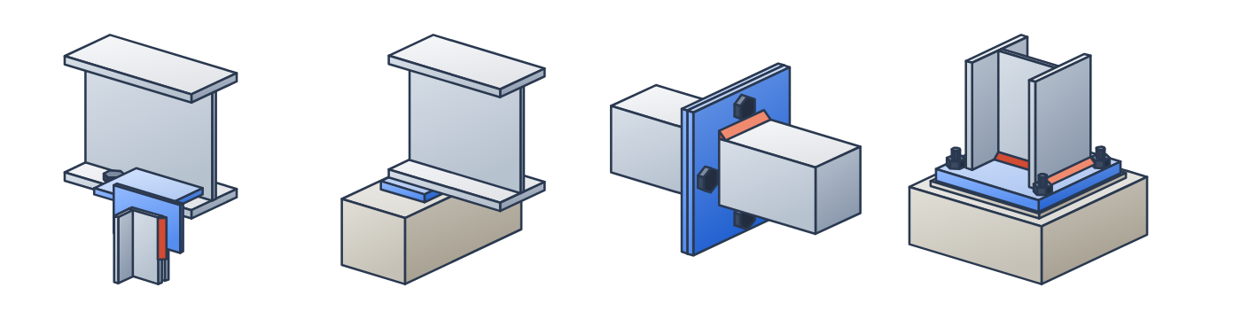
These three connection types carry an axial force (tension in a hanger or strut, a bearing reaction on a wall). They share the single-plate editor's layout: the input panel on the left with collapsible sections and pins, the status bar, the drawings with click-to-edit, the output bar, and the All checks and Code compliance tabs. They are described here type by type. For how to read the checks, see Checks and compliance.
Creating one #
- Click New connection in a project.
- On the first step of the wizard, under Tension and bearing connections, click Hanger, Beam bearing plate or HSS strut end plate.
- ILX creates the connection with the standard defaults and your project's defaults for that type, and opens it in its own editor. The defaults reproduce the AISC Design Example of each type, so a new connection starts from a verified design.
Save as project defaults stores materials, bolts, welds and the method for this type only. Members and loads are never saved as defaults.
Loads for axial connections #
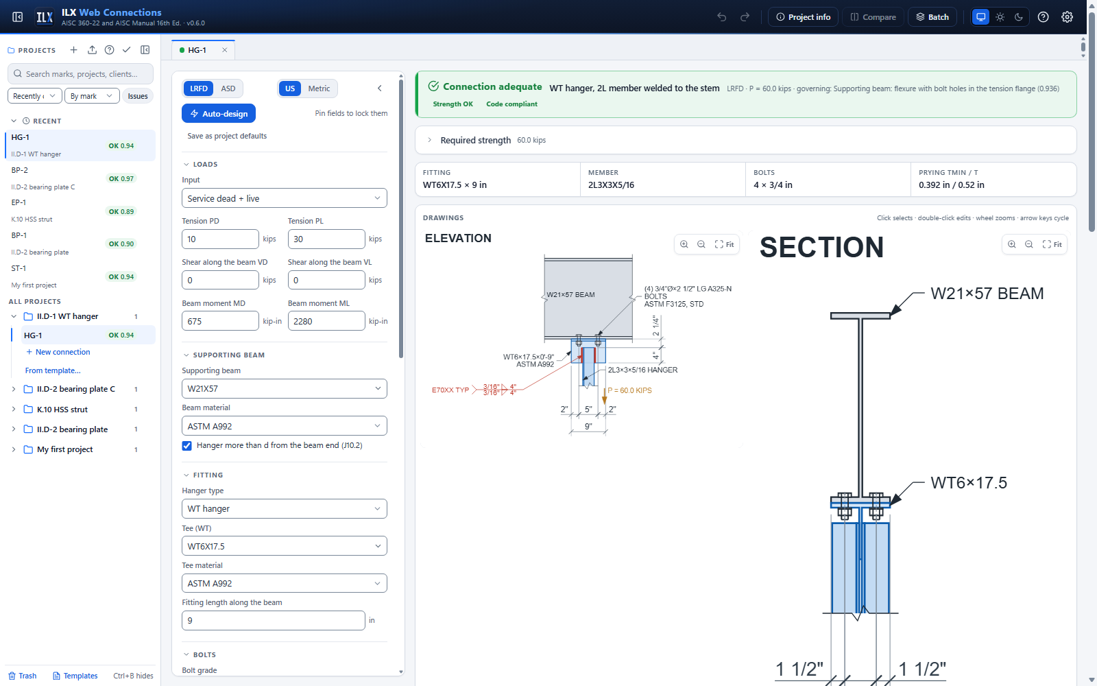
The Loads section works the same way for the three types. The load symbol is P (tension) for the hanger and the strut and R (reaction) for the bearing plate.
| Input | What you enter | What ILX uses |
|---|---|---|
| Service dead + live | PD, PL (or RD, RL) | LRFD: max(1.2D + 1.6L, 1.4D). ASD: D + L. |
| Service components → ASCE 7 combinations | D, L, Lr, S, W, E | Every ASCE 7-22 2.3 (LRFD) or 2.4 (ASD) combination. W and E are applied with both signs. Each check reports its governing combination. |
| Required strength | Pu or Pa, entered directly | That value |
| Factored load cases | A table of named cases | Each case. The checks are enveloped across the cases. |
For the hanger there are two extra inputs:
- Shear along the beam (V), for an inclined hanger. It reduces the bolt tension through AISC 360-22 Eq. J3-3a/b (F'nt).
- Beam moment at the hanger (MD, ML or M). It drives the flexure check of the supporting beam with bolt holes in its tension flange (AISC 360-22 F13.1).
For the bearing plate with anchor rods, enter the required uplift and horizontal force on the rods directly.
Hanger connections #
Hanger fitting #
| Hanger type | Fitting | The hanging member attaches to |
|---|---|---|
| WT hanger | A WT flange bolted to the beam bottom flange. There are two bolt lines at gage g and n rows at spacing s along the beam. | The tee stem |
| Double-angle hanger | Two angles back to back. Their outstanding legs are bolted to the beam flange. | A plate between the vertical legs. It is bolted in double shear, or fillet-welded along the leg toes. |
| Welded plate hanger | A plate fillet-welded to the beam flange (both faces). It runs along the web, or across the flange. | The plate |
Fitting length along the beam is L. The end distance is (L − (n − 1) s)/2 and is checked against AISC 360-22 Table J3.4.
Bolt layout (WT and double-angle hangers):
- Rows along the fitting (default). n rows at spacing s, centred on the fitting length.
- 4 bolts at the corners. One bolt near each corner of the fitting flange. The two rows sit at the corner end distance e from each end of the fitting, so s = L − 2e. The gage g across the beam is still yours to set. If L − 2e is less than 2⅔ d, the bolts clash and ILX reports that the layout is not feasible.
Corner bolts are end bolts in Manual Figure 9-4, so p = min(e, 1.75b) + min(s/2, 1.75b). ILX also checks that the hanger force reaches the corner bolts. The force spreads at 30° from the member attachment up through the stem to the flange, over a length Ls ≤ L:
- the two bolts on a gage line share that length, so p ≤ Ls/2;
- when a bolt lies beyond the loaded length, b is measured diagonally to the end of it: b = √(b² + (s/2 − Ls/2)²).
With shear V, ILX also checks bearing and tearout at the fitting ends and block shear of the fitting flange. The load-spread limit is ILX's own conservative addition to the Manual method; the calculation shows each step.
Hanging member #
- Member:
- Double angle (2L): two angles straddling the stem, as in II.D-1.
- Plate: lapped on one face of the stem, or placed between the fitting angles.
- Attachment:
- Fillet-welded. For a 2L, the welds are on the heel and toe of each angle, with the weld length entered per line.
- Bolted. Enter the number of bolts, their spacing, the member end distance and the stem bottom edge distance.
Hanger checks #
- Bolts to the beam, tension with prying (Manual Part 9). ILX uses both forms of the Manual method:
- Solution Method 2: the minimum fitting flange thickness tmin from β and α' (Manual Eqs. 9-35 to 9-37). It is compared with the flange thickness. This is the II.D-1 calculation.
- Method 1: the available tension per bolt, Q × Tc (Manual Eqs. 9-38 to 9-40), compared with the tension per bolt.
Both use the tributary length per bolt from Manual Figure 9-4: p = min(le, 1.75b) + min(s/2, 1.75b) for an end bolt. With shear, Tc uses F'nt (AISC 360-22 J3.8).
- The supporting flange. Prying in the beam flange, with b and a measured on the beam: the local bending of the supporting flange. For a welded plate across the flange, flange local bending is checked by AISC 360-22 J10.1 (6.25 Fyf tf²; halved near the beam end; not required when the plate is narrower than 0.15 bf).
- Bolt shear and slip. Bolt shear applies only with V. Slip-critical joints use ksc = 1 − Tu/(Du Tb nb) (Eq. J3-5).
- The fitting. Shear yielding and shear rupture of the tee or angle flanges (J4.2).
- The stem or plate:
- tensile yielding on the Whitmore section (lw = w + 2 l tan 30°, not more than the fitting length);
- shear rupture of the base metal at the welds;
- block shear, U- and L-shaped (J4.3).
For a bolted member, rupture on the Whitmore section and L-shaped block shear at the bolts are checked as well.
- The member.
- Tensile yielding (D2).
- Tensile rupture with the shear lag factor U from AISC 360-22 Table D3.1: Case 4 for longitudinal welds, U = 3l²/(3l² + w²)(1 − x̄/l); Case 2 for bolts.
- Base metal shear rupture along the welds.
- Bolt shear, bearing and tearout, and block shear when bolted.
- The welds. Strength (J2.4, kds = 1.0 for the longitudinal member welds; 1.5 for the transverse welds of a plate hanger to the flange). The minimum length lmin (Manual Eq. 8-2) is reported. The minimum and maximum fillet size and the 4w minimum length are checked.
- The supporting beam. Web local yielding under the hanger force (J10.2: 5k + lb, or 2.5k + lb within d of the beam end). Flexure with holes in the tension flange (F13.1) when a beam moment is entered.
- Detailing.
- Spacing, edge distances (Table J3.4) and the J3.6 maximums.
- The bolt lines must lie on both flanges and clear the web and stem fillets (feasibility).
- Tightening clearance (Manual Tables 7-15/7-16).
- A fitting no wider than the beam flange.
- Pretensioned bolts under cyclic loading.
- Fatigue (Appendix 3). With Cyclic loading ticked, the cycle count and the cyclic tension range (a fraction of the live tension PL, or the range of P entered) as for the single plate; see Fatigue (Appendix 3). The details: the bolts in tension with prying (Table A-3.1 Case 8.5, G, on the tensile stress area At, Eq. A-3-7: 20 % of the cyclic load for pretensioned bolts, else the load plus prying, Section 3.4(b)); this replaces the earlier design-load bolt check. A welded plate hanger: the plate at its fillets (Case 5.7, C and C″) and the fillets (Case 8.2, F). The hanging member: welded, the member at the ends of its longitudinal welds (Case 4.1) and the fillets (Case 8.2); bolted, the member at the holes (Section 2).
Beam bearing plates #
Bearing plate inputs #
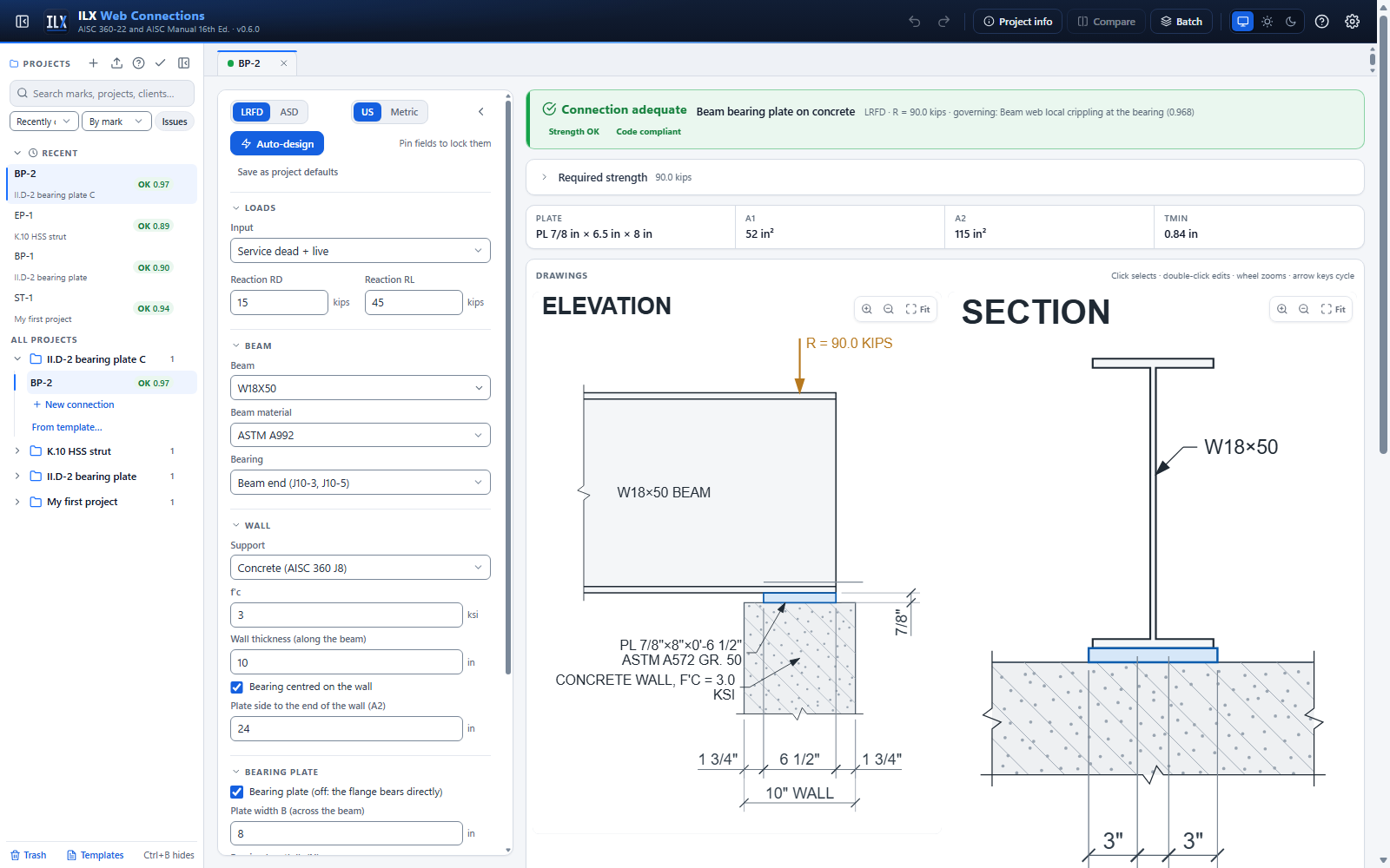
- Beam, Beam material and Bearing:
- Beam end (an end reaction): AISC 360-22 Eqs. J10-3 and J10-5a/b.
- Interior: Eqs. J10-2 and J10-4.
- Wall:
- Support: concrete (AISC 360-22 J8) or masonry (TMS 402-22).
- f'c or f'm.
- Wall thickness along the beam.
- The bearing position: centred, or a wall face to the bearing distance.
- The side distance to the end of the wall.
These set A2, the largest area geometrically similar to and concentric with A1 that fits on the wall.
- Bearing plate:
- Untick it to check the beam flange bearing directly, as in II.D-2 Solution A.
- Width B, bearing length lb, thickness and material.
- Count the beam flange with the plate is an ILX option, off by default. With it on, the plate and flange share the cantilever moment at the web, and the plate alone carries it beyond the flange tips. The Manual's method, which ignores the flange, is conservative.
- Anchor rods (optional). The rods run through the plate outside the flange, or through the flange.
- Inputs: 2 or 4 rods, diameter, grade (F1554 Gr. 36, 55 or 105, or A36) and gage.
- Hole sizes and plate washers follow Manual Table 14-1.
- Beam bearing stiffeners (J10.8): None (default; saved connections are unchanged), Design when required (when web local yielding or crippling fails) or Provided (as entered), with the thickness (provided only), width (0 = max), Full or Half depth (from the bottom flange), corner clip, fillets, material, Finished to bear on the bottom flange (J7) (on by default) and the electrode.
Bearing plate checks #
- Web local yielding and web local crippling at the bearing (J10.2 and J10.3). The Manual Table 9-4 constants (φR1, φR2, φR5, φR6, or R3/R4 when lb/d ≤ 0.2) and the required bearing length lb,min (Manual Eqs. 9-60 to 9-63) are shown in the calculation.
- Bearing on the support.
- Concrete: Pp = 0.85 f'c A1 √(A2/A1) ≤ 1.7 f'c A1 (J8-1, J8-2), φc = 0.65, Ωc = 2.31. The calculation also gives the required area A1,req and plate width B,req.
- Masonry: TMS 402-22. Bearing area A1 √(A2/A1) ≤ 2 A1; strength design 0.8 f'm with φ = 0.60; allowable stress design 0.33 f'm.
- Plate thickness (Manual Part 14): n = B/2 − kdes, tmin = √(2 Ru n² / (φ Fy B lb)). Without a plate, the beam flange is checked with B = bf.
- Geometry.
- The bearing must lie on the wall (feasibility).
- lb ≥ kdes.
- B ≥ bf (advisory).
- The rod holes must clear the flange and fit in the plate.
- Bearing stiffeners (when selected). The pair over the centre of the bearing carries the whole reaction: two stiffeners plus a 12tw (end reaction) or 25tw (interior) web strip as a column, Lc = 0.75h (J10.8, J4.4, Chapter E); J10.8 width, thickness (≥ half the plate thickness, ≥ width/16) and length; corner clips; fitted bearing on the flange (J7, 1.8 Fy Apb) or flange fillets; web fillets; beam web shear rupture along the welds. When the stiffeners are adequate, web local yielding and crippling become recommendations (bearing stiffeners required). The drawings show the pair edge-on in the elevation and face-on in the section. The plate thickness and the bearing on the support are unchanged by the stiffeners.
- Anchor rods. Tension with shear (J3.8, Fnt = 0.75 Fu for threaded rods) and shear. ILX does not check the anchorage in concrete (ACI 318 Chapter 17); use the base-plate type or an anchor design program for that.
HSS strut end plates #
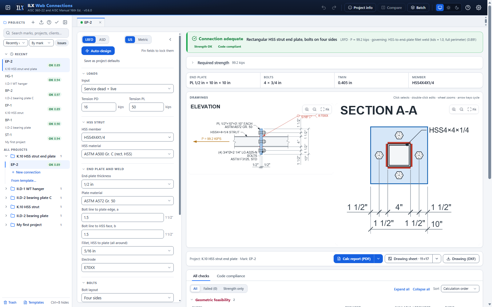
End plate inputs #
- HSS member (rectangular or round) and its material.
- End plate:
- thickness and material;
- a, from the bolt line to the plate edge;
- b, from the bolt line to the HSS face.
The plate size follows from the HSS size plus 2(a + b).
- Bolts.
- Rectangular HSS, Bolt layout:
- Along the sides: four sides or two sides, and the bolts per side and their spacing.
- 4 bolts at the corners: one bolt beyond each HSS corner, at b from both faces. The plate is B + 2(a + b) by H + 2(a + b).
- Round HSS: the number of bolts on the circle of radius D/2 + b.
- Rectangular HSS, Bolt layout:
- Weld. A fillet all around the HSS.
The drawing shows a bolted splice of two identical end plates, as in K.10.
End plate checks #
- Rectangular HSS. Manual Part 9 prying with Fy in place of Fu (Willibald, Packer and Puthli 2003). The tributary length p is the full plate width divided by the bolts per side (Packer and Olson 2023, DG24 2nd Ed.). ILX checks:
- the minimum end-plate thickness (Solution Method 2, as K.10);
- the available bolt tension with prying (Method 1);
- that the bolts lie within the HSS corners;
- a ≤ 1.25 b (a larger a is not effective).
- Rectangular HSS, corner bolts. DG24 (1st and 2nd Ed.) covers only bolts that are not beyond the HSS corners, so there is no published method for corner bolts. ILX uses the same Manual Part 9 prying model with these conservative choices:
- Lever arm. b is the diagonal distance from the bolt to the rounded HSS corner: bd = √2 (b + r) − r, with r = 2t.
- Edge distance. a is the orthogonal edge distance, the shorter of the two prying arms.
- Tributary length. p = min[2(B + H + π b)/4, 4 √(b′(a + bd))], from DG24 2nd Ed. Eqs. 7-17 and 7-18.
- Plate strength. Fy in place of Fu, as for the other rectangular layouts.
The tightening clearance is measured to the HSS corner. Expect a thicker plate than with bolts on four sides. For the K.10 strut, the corner layout needs a 3/4 in. plate where four sides need 1/2 in.
- Round HSS. DG24 Eqs. 5-5 to 5-13:
- tp ≥ √(2 Pr / (φ Fyp π f3));
- n ≥ (Pr / rn)[1 − 1/f3 + 1/(f3 ln(r1/r2))].
Bolt pitch on the circle is checked as well.
- Weld. Rn = 0.60 FEXX (√2/2) w l kds with kds = 1.0. AISC 360-22 J2.4(a)(2) gives kds = 1.0 for fillet welds at the end of a rectangular HSS in tension. l is the full perimeter, 2(B + H) or π D, as in K.10. The calculation also gives the required weld size in sixteenths. The minimum fillet follows Table J2.4.
- HSS member. Tensile yielding and rupture (D2; U = 1.0 for an all-around weld to a cap plate).
- Detailing. The edge distance a must meet Table J3.4. The bolt must clear the HSS wall and its weld, and ILX also checks the tightening clearance b ≥ C1. Bolts in fatigue must be pretensioned.
- Fatigue (Appendix 3). With Cyclic loading ticked: the bolts in tension with prying (Case 8.5, G), the HSS wall at the toe of its weld (Case 5.7 toe crack, C; the weld is on one side of the wall, and Table A-3.1 has no root-crack case for it, so the engineer verifies the root) and the weld (Case 8.2, F); see Fatigue (Appendix 3).
Drawings, reports and verification #
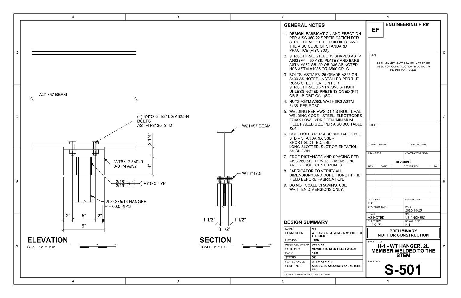
- Drawings. Every type has two views:
- Hanger: an elevation along the beam and a section across it.
- Bearing plate: an elevation with the wall cut in section and hatched (concrete, or masonry lines), and a section across the beam.
- HSS strut: an elevation of the splice and Section A-A at the end plate.
Members are drawn from their real AISC profiles. Bolts are drawn realistically (head, washer, shank, nut). Welds carry AWS A2.4 symbols, including the all-around symbol on the HSS weld. Click an element to select it; double-click to edit its inputs in a popover.
- Sheets and reports. The drawing sheet (PDF or DXF, all three sizes) and the calculation report work as for the single plate. The sheet's design summary reads REQUIRED TENSION or REQUIRED REACTION.
- Auto-design.
- Hanger: the tee, the bolt rows and diameter, and the weld size and length.
- Bearing plate: the plate thickness, width and length.
- HSS strut end plate: the plate thickness, the bolt diameter and the weld.
Pinned fields are kept.
- Verification. Design Examples II.D-1, II.D-2 (Solutions A, B and C) and K.10 are reproduced end to end in LRFD and ASD. Every limit state is within 1 % or 0.5 kip of the published value. Two rows carry the example's own rounding as a documented tolerance: the II.D-1 Whitmore available strength and the K.10 α'. The round HSS method is benchmarked against Packer (2023). See Verification.