
Designing a skewed double bent-plate connection
A skewed beam frames into a girder web at a plan angle. Two bent plates, one on each face of the beam web, follow the skew. Each plate has two flat legs:
- a support leg lying flat on the girder web;
- a beam leg lying flat on the beam web.
The bend between the legs has an inside radius R.
ILX follows AISC Design Example II.A-10 (Design Examples v16.0, pp. IIA-115 to IIA-121). The defaults of a new skewed connection are that example. It verifies to within 1 % in LRFD and ASD; see Verification.
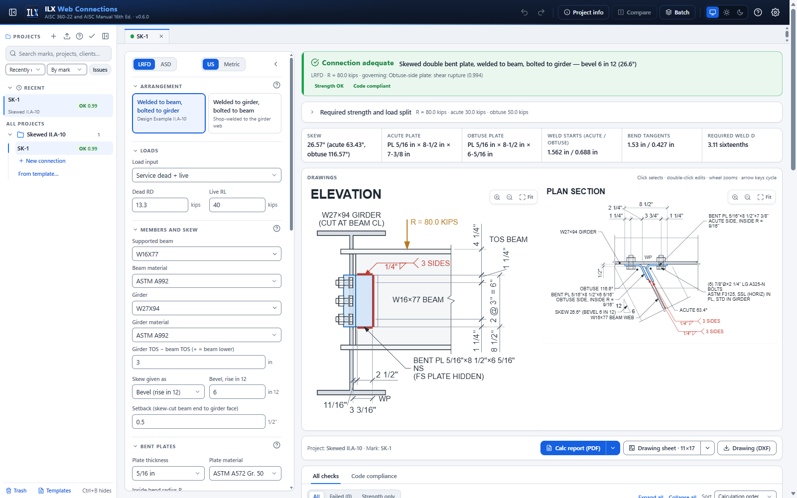
The editor workflow #
The editor works like the single-plate editor. Every change re-runs the design, and the status bar, drawings and checks update.
- Choose LRFD or ASD and US or Metric.
- Choose the arrangement.
- Enter the loads.
- Enter the members and the skew.
- Set the plates, bolts and welds.
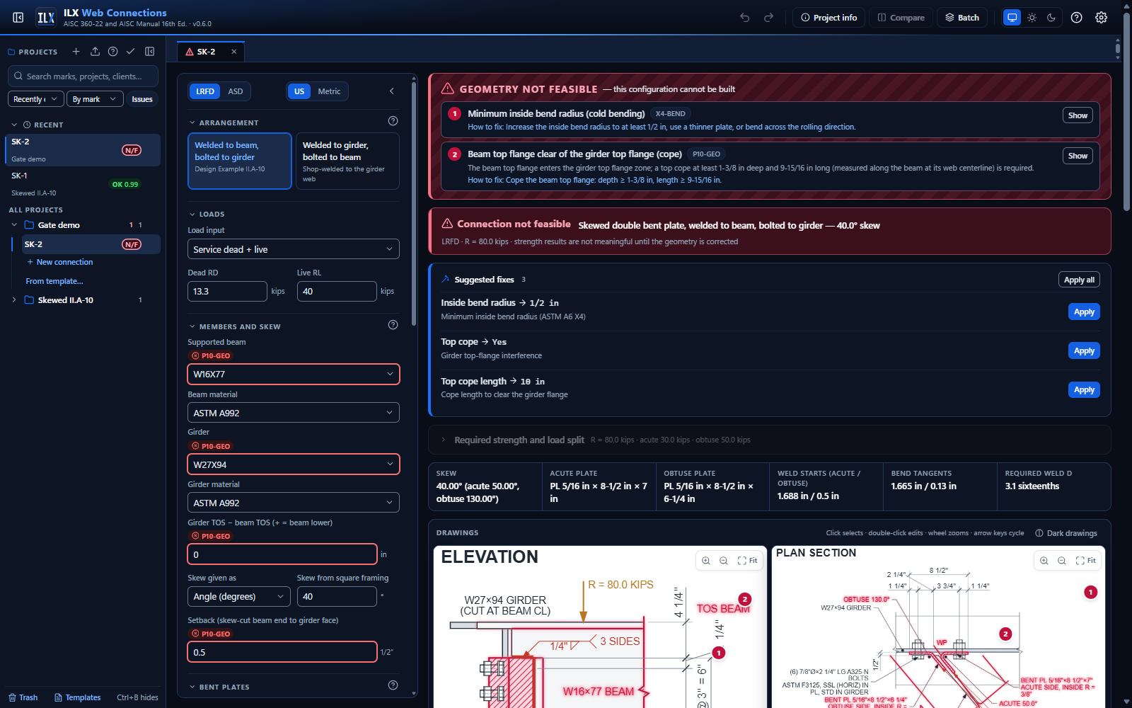
- Fix whatever the status bar, the GEOMETRY NOT FEASIBLE banner or the checks report.
- Create the calc report and the drawing sheet from the output bar.
To create one, choose New connection in a project. In the wizard, under Connection type, pick Plate in the Simple shear group, then Skewed bent plate under Plate type. The wizard asks for the beam, the girder, the bevel, the arrangement and the service loads. Everything else starts from II.A-10.
Arrangement #
| Arrangement | Shop | Field | Bolts | Welds |
|---|---|---|---|---|
| Welded to beam, bolted to girder (II.A-10) | plates welded to both faces of the beam web | support legs bolted to the girder web | one vertical line per plate, single shear | C-shaped fillets on the beam web |
| Welded to girder, bolted to beam | plates welded to the girder web | beam legs bolted through the beam web | one line through both plates and the web | C-shaped fillets on the girder web |
The second arrangement applies the II.A-10 procedure with the two members' roles exchanged. The split between the plates uses the weld-group centroids on the girder instead of the bolt lines. The welds are designed for the load at the work point. The beam web carries the full reaction in bearing.
Bent plates chooses Two bent plates (II.A-10), the default, or Single bent plate (Manual Fig. 10-37). For a single plate, Face of the beam web puts it on the obtuse face (the default) or the acute face. Both arrangements above work with one plate. See Single bent plate below.
Members and skew #
- Supported beam and Girder: W, M, S or HP shapes, with their materials.
- Girder TOS − beam TOS (+ = beam lower). In II.A-10 the beam is 3 in. below the girder.
- ILX checks that the plates sit in the girder's clear web, between the fillets.
- It also checks that the beam flanges clear the girder flanges. If a flange enters the girder's flange zone, the connection is NOT FEASIBLE. ILX then suggests a cope and its required depth and length. The length is measured along the beam to clear the acute flange tip.
- Skew given as:
- Bevel (rise in 12), e.g. 6 in 12 = 26.57°;
- Angle (degrees) from square framing, less than 75°.
- Setback: the clear gap from the skew-cut beam end to the girder face, measured perpendicular to the girder (the end is cut parallel to the girder web). It must be positive.
ILX names the two plates by the side of the beam they are on:
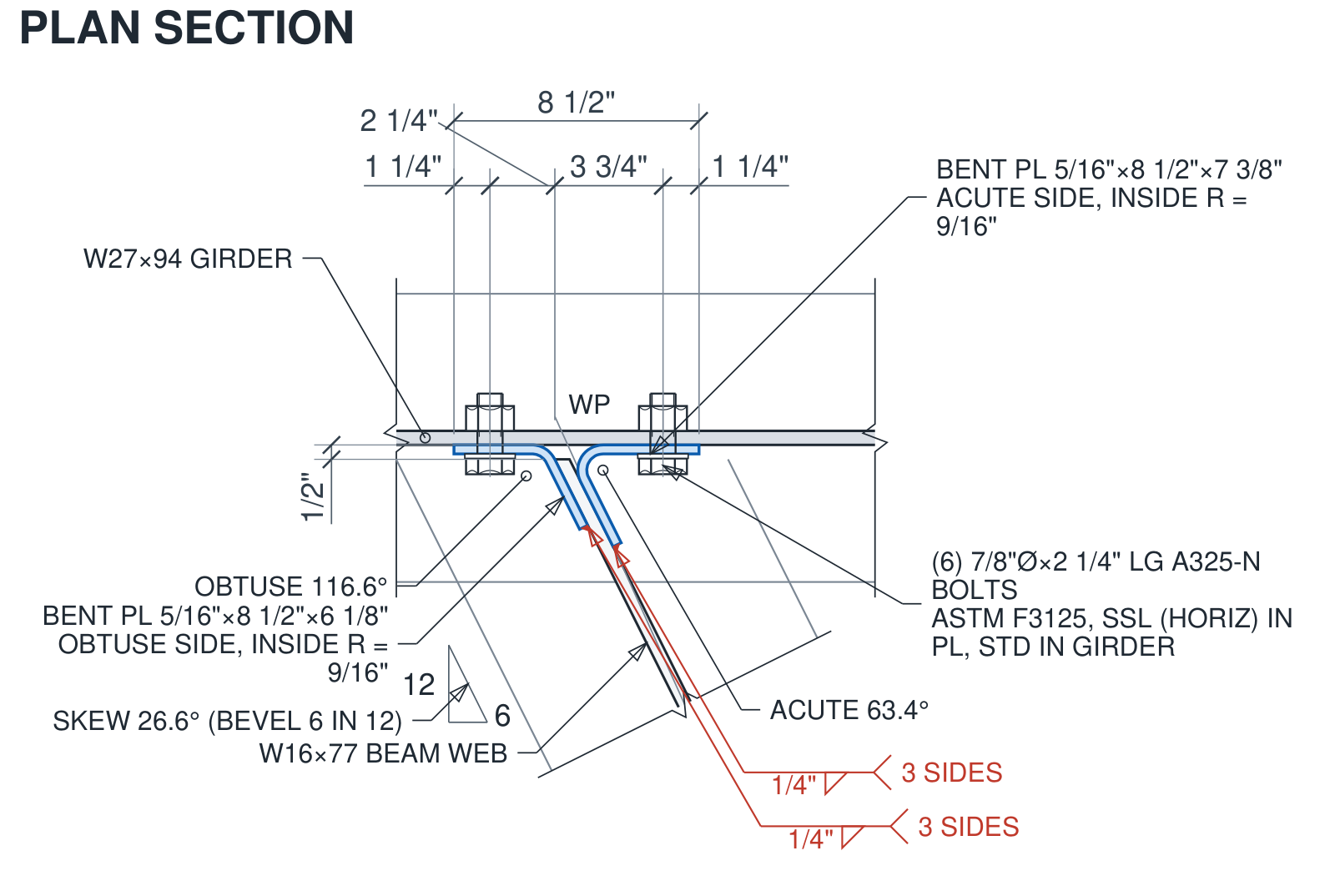
- Acute side: included angle 90° − φ. In II.A-10 this is bent plate A, 63.4°.
- Obtuse side: included angle 90° + φ. In II.A-10 this is bent plate B, 116.6°.
The work point (WP) is the beam centerline at the girder face. Bolt lines and weld starts are measured from it.
Bent plates #
- Plate thickness and Plate material. II.A-10 uses 5/16 in. A572 Gr. 50.
- Inside bend radius R. ILX checks R against the minimum inside radius for cold bending of ASTM A6 Appendix X4, Table X4.1, for the plate's steel group and thickness. That table is reproduced in the AISC Manual Part 10.
- For example, 1.5t for A36 or A572 Gr. 50 up to 3/4 in. thick.
- Tick Bend line parallel to the final rolling direction to apply the table's ×1.5.
- A radius below the minimum makes the connection NOT FEASIBLE.
- Top of beam to top of plates and Lev. The plate depth is 2 Lev + (n − 1) s.
- Cb, plate lateral-torsional buckling (F11): your input, default 1.84, for the flexure check at the bend (an ILX addition). Neither the Manual (skewed connections, pp. 10-88 and 10-89) nor Design Example II.A-10 gives a Cb. 1.84 is the single-plate value of Manual Eq. 10-8. The report shows "Cb = x (engineer input)".
The key-geometry strip shows:
- each plate's size: thickness × depth × developed length, measured at mid-thickness and rounded up to 1/16 in.;
- the weld starts and the bend tangents.
Bent-plate bolts #
- Grade, diameter, threads, joint (bearing or slip-critical) and surface class: all grades, thread conditions and joint types.
- Bolts per line n, spacing s, and Leh, the bolt line to the end of the bolted leg.
- The bolt line positions:
- Welded to beam: Acute bolt line from WP and Obtuse bolt line from WP, both along the girder. II.A-10 uses 3 3/4 in. and 2 1/4 in.
- Welded to girder: Bolt line from WP, a, along the beam.
- Holes in plates and holes in the girder (or beam) web. II.A-10 uses short slots, horizontal (SSL horizontal), in the plates and standard holes in the girder.
- Bolt-line eccentricity:
- None (load split by statics, II.A-10): each line takes its share of the reaction.
- From the work point: a conservative option.
- Given: a value you enter.
- Bolt group strength: (C/n) × Σ per-bolt, the "shear transfer at bolt holes" of the Design Examples, or C × the weakest bolt.
The plate is checked for the following, as II.A-10 does:
- the bolts, by the least of bolt shear, plate bearing or tearout, and girder-web bearing or tearout, at each bolt;
- plate shear yielding;
- shear rupture;
- block shear.
ILX adds two checks the example does not make, flagged in their titles:
- in-plane flexure of each plate at the bend;
- the Manual Eq. 10-8 shear and flexure interaction there.
Bent-plate welds #
- Fillet size and electrode.
- Weld shape: C-shape (3 sides), top and bottom only, or vertical at the toe only. kl is the horizontal weld length.
- Weld group location:
- Averaged, both plates (II.A-10) places both weld groups at the average of the two weld starts. This follows the example: "the locations of the weld groups will be averaged and considered identical".
- Each plate its own uses each plate's own location.
- Acute / obtuse weld start from WP. By default, From the bend geometry starts the welds where the beam leg leaves the bend (the tangent point) or at the beam end, whichever is farther, rounded up to 1/16 in. You can also enter a distance.
- A weld that starts on the bend or past the beam end is NOT FEASIBLE.
- For II.A-10's acute plate, the bend geometry gives 1.53 in.; the published value is 1 9/16 in.
Each weld group is solved by the instantaneous-center method (Manual Part 8) with the load at the work point. Table 8-8 is the example's equivalent. The required size D and the coefficient C are shown in the calc card. ILX also checks:
- the base metal: tmin = 6.19 D / Fu for plates on both faces of the beam web (Manual Eq. 9-7), or 3.09 D / Fu on one face of the girder web;
- minimum and maximum fillet size (Table J2.4; t − 1/16 in. along the plate edge);
- kl ≥ 4w;
- the lap length.
The bent-plate fillets lie on the flat legs, so they are lap fillets, not skewed T-joint fillets. The dihedral angles at the bends are labeled in the plan view for reference. A recommendation reports the acute opening angle, against the 30° welding-access guidance.
Geometry gate #
Any of the following marks the connection NOT FEASIBLE:
- the inside radius is below the ASTM A6 X4 minimum;
- the setback is zero or negative;
- a weld starts on the bend or past the beam end;
- a bolt head or washer would sit on the bend;
- the plates run into the beam or girder flanges;
- a beam flange clashes with a girder flange without a cope.
Tightening clearance checks the distance from each bolt to the other leg of the same plate against the impact-wrench clearance C1. On the acute side it also checks the beam top flange. A shortfall is NG (detailing), not NOT FEASIBLE: the bolt can still be tightened from the other side.
A skew over 45° raises a recommendation, because the Manual's skewed details stop at 45°.
Single bent plate #
As the skew grows, the bolts on the acute side need a larger gage on the support to leave room to enter and tighten them. The AISC Manual (16th Ed., Part 10, pp. 10-88 and 10-89) says that if that gage becomes objectionable, "a single bent plate, illustrated in Figure 10-37, may provide a better solution". Choose Single bent plate under Bent plates, then the face of the beam web it sits on.
The Manual's rules, and what ILX does with each:
- Load at the work point. "The load is assumed to be applied at the point where the skewed beam centerline intersects the face of the supporting member." The one plate carries the full reaction R; there is no load split.
- Bolts. "Both the shop and field bolts should be designed for shear and the eccentric moment." The bolt group is always solved by the instantaneous-center method (Manual Part 7) with e = WP to the bolt line: along the girder when bolted to the girder, along the beam (a) when bolted to the beam. The Bolt-line eccentricity option does not apply and is hidden. Each bolt is the least of bolt shear (single shear), plate bearing or tearout, and girder-web or beam-web bearing or tearout.
- Welds. Each weld group is solved by the instantaneous-center method (Manual Part 8) at its own location from the work point. Weld group location does not apply and is hidden. "A C-shaped weld is preferable to avoid turning the beam during shop fabrication": another weld shape raises a recommendation.
- Base metal. With the plate welded to one face of the beam web, tmin = 3.09 D / Fu (Manual Eq. 9-6). Welded to the girder, the girder-web rule is unchanged.
- Plate. Shear yielding, shear rupture and block shear are checked for the full R.
- Flexure. "Single bent plates should be checked for flexural strength." The Manual does not say where or how. Because each bolt and weld group is designed for a load through the work point, ILX takes the in-plane moment at a section as R × the distance from the work point. It checks:
- flexural yielding (Spec F11) with e = the larger of WP to the bolt line and WP to the weld start;
- flexural rupture through the bolt holes, Fu Znet, with e = WP to the bolt line;
- the Manual Eq. 10-8 shear and flexure interaction.
This is how the Manual checks a conventional single-plate connection at its bolt line. The calc steps say that the section and load path are ILX's choice.
- Geometry. The bend radius, weld-on-the-flat, bolt-head-on-the-flat, tightening clearance, beam clearance and flange checks apply to the one plate. Only that side's bolt-line and weld-start inputs are shown.
- Range of skews. Table 10-14B recommends single bent plates for skews from 4 in 12 to 12 in 8 (18.4° to 56.3°). Outside that range ILX raises a recommendation, not a failure.
The plan view draws the one plate. The elevation draws it as the near plate, seen from its own face of the beam web. The report and the status bar title the connection "Skewed single bent plate".
What the single-plate option does not cover:
- the all-bolted single bent plate (Fig. 10-37(a), Table 10-14A, with its D and H dimensions by bevel and 1 in. maximum bolts);
- the wrapped configuration of Fig. 10-37(c). Only the conventional configuration is designed;
- the small out-of-plane offset between the work point and the plate on the beam web (half the web plus the plate). The Manual gives no rule for it, and a recommendation says it is not included.
Copes #
Tick Top cope or Bottom cope and enter c and dc; the girder-flange check proposes the values. ILX then checks:
- the coped web in shear;
- the single-cope local flexure (Manual Part 9, Dowswell 2018), with e measured from the work point to the cope face;
- the reentrant radius (AISC 360-22 M2.2).
A double cope is accepted, but its local flexure is not checked here; a recommendation says so.
Drawings and outputs #
- Plan section: the true skew, with:
- the girder web, with its bottom flange hidden;
- the skew-cut beam web;
- both bent plates, with their bends;
- the bolts, drawn realistically through the support legs;
- the toe fillets in section, with their AWS A2.4 symbols;
- the acute and obtuse included angles, the bevel triangle, and the dimensions along the girder.
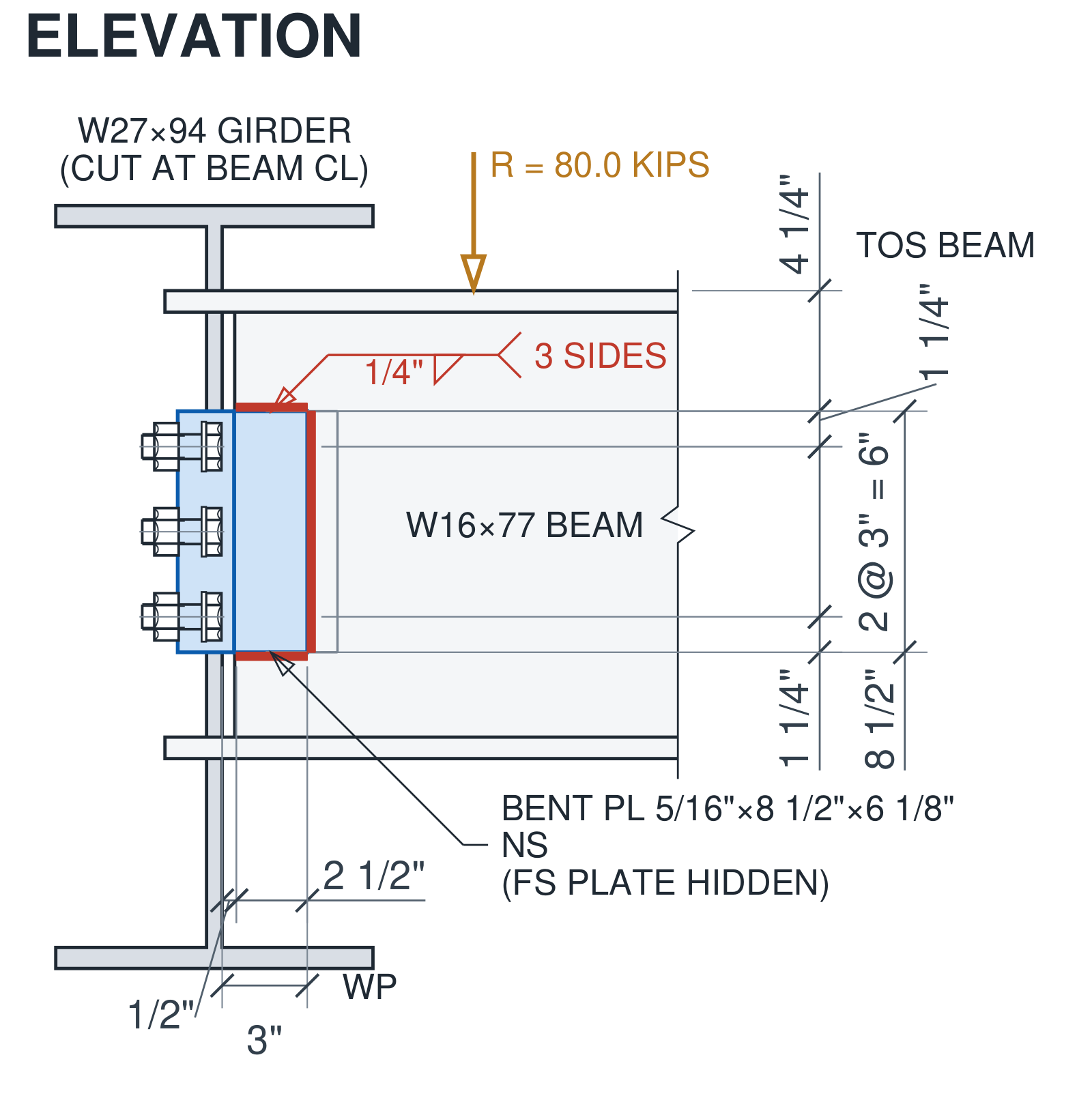
- Elevation, looking normal to the beam web from the obtuse side:
- the girder cut at the beam centerline;
- the near plate, with its weld strips and side-view bolts;
- the far plate, hidden;
- the dimensions from the work point and from the top of beam.
Click an element to select it and double-click to edit it in place, as in the single-plate editor. The calc report and the drawing sheet (PDF and DXF, at every sheet size) come from the output bar.
Limits #
- One vertical bolt line per plate.
- Shear only: no axial load and no load combinations beyond D + L or a given required strength.
- No auto-design.
- Skewed single plates and skewed end plates are not part of this type. Their Manual Part 10 text (gap, bevel and the Table 10-14C weld details) is documented in research/24 for a later version.