
Designing a column base plate
The base plate type designs a column base plate on a concrete pier or footing. It covers axial compression and uplift, major-axis moment, shear, the anchor rods, the column-to-plate welds and the OSHA erection check. Concrete anchorage is checked to ACI 318-19 Chapter 17.
When to use it #
Use it for an exposed column base: a W, M, S, HP, HSS or Pipe column on a base plate, with four or more cast-in anchor rods in a concrete pier or footing. Shear goes by friction, by a shear lug or through the anchor rods.
It does not cover embedded column bases, stiffened base plates or moment about the column minor axis. See Limitations.
Creating a base plate in the wizard #
- Select New connection and, in the Connection type step, pick Base plate in the Column bases group.
- The base-plate wizard opens, titled New column base plate. It has one page:
- Connection mark: the next free mark, BP-1, BP-2 and so on.
- Column: type to search the W, HP, HSS and Pipe shapes.
- Loads: Service D + L (dead and live PD, PL, MD, ML, VD, VL) or Required strength (P, M, V). P is + compression, − uplift.
- Shear transfer: Friction, Shear lug or Anchor rods.
- Select Create. Connection type takes you back to the type choice.
Everything else starts from the standard base-plate defaults and is edited in the editor. The method, units and electrode come from the project defaults. For an HSS or Pipe column the wizard sets fillet welds and A500 Gr. C.
The base-plate wizard has no Auto-design the connection option. Run Auto-design from the editor after you create the connection.
Inputs in the editor #
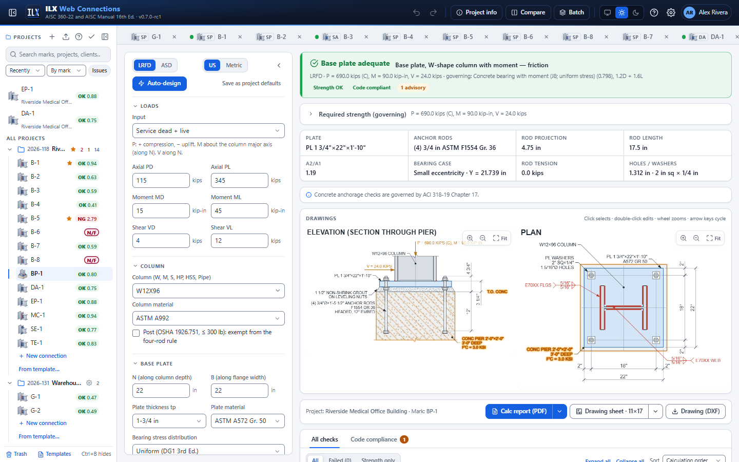
The editor works like the other connection editors (see The editor workflow). The toolbar has LRFD or ASD, US or Metric, Auto-design and Save as project defaults. Save as project defaults stores this type's materials, hardware and methods, not the members and loads.
In metric, all lengths are in mm, forces in kN, moments in kN-m and stresses in MPa. Rod diameters stay in inches, with the mm value shown.
Above the drawings, a key-results strip shows the Plate, Anchor rods, Rod projection, Rod length, A2/A1, Bearing case (with the bearing length Y), Rod tension and Holes / washers. A note states that the concrete anchorage checks are governed by ACI 318-19 Chapter 17.
Loads on the base plate #
Choose how you enter the loads with Input. Signs: P is + compression, − uplift. M acts about the column major axis (along N). V acts along N.
Biaxial loads. Every input mode also takes a minor-axis moment My, which compresses the +B edge, and a shear along B, Vy:
- Service D + L: MyD, MyL, VyD, VyL.
- ASCE 7 components: the My and Vy columns.
- Required strength: My, Vy.
- Cases: the My and Vy columns.
Leave them at 0 for a uniaxial design; the results are then exactly the uniaxial ones. With My, the base plate is designed to AISC Design Guide 1, 3rd Ed. §4.3.11 (Example 4.7-14). See Biaxial bending under the checks.
| Input | Enter | Combinations used |
|---|---|---|
| Service dead + live (default) | Axial PD, Axial PL, Moment MD, Moment ML, Shear VD, Shear VL | LRFD: 1.2D + 1.6L, plus 1.4D when its axial or moment is larger. ASD: D + L. |
| Service components → ASCE 7 combinations | P, M and V for D, L, Lr, S, W and E | Every ASCE 7-22 LRFD (2.3) or ASD (2.4) combination. W and E act in both directions. |
| Required strength (Pu, Mu, Vu) | Axial Pu, Moment Mu, Shear Vu (Pa, Ma, Va in ASD) | None (used as entered) |
| Factored load cases (table) | Named cases, each with P, M and V. Select + Add case. | Each case is checked |
- Units: forces in kips (kN), moments in kip-in (kN-m).
- The axial load keeps its sign. Moment and shear are designed by magnitude, because the rod pattern and pier are symmetric.
- Negative ASCE 7 components model reversal. The 0.9D and 0.6D combinations give the net-uplift cases.
- With more than one combination or case, a Load combinations table lists each one with P (+C), M, V, ratio and status. The governing one is tagged governs, and each check shows its governing combination.
- The OSHA erection checks run as their own case, OSHA 1926.755 erection (300 lb at 18 in.).
Column member #
| Field | Options and notes |
|---|---|
| Column (W, M, S, HP, HSS, Pipe) | AISC shape. Rectangular and round HSS and Pipe are welded all around. |
| Column material | Any steel for W, M, S and HP. A500, A1085 and A53 Gr. B for HSS and Pipe. |
| Post (OSHA 1926.751, ≤ 300 lb): exempt from the four-rod rule | Exempts the column from the four-rod rule and the erection check. Also lowers the recommended plate thickness to 1/2 in. |
Base plate dimensions and bearing method #
| Field | Options and notes |
|---|---|
| N (along column depth) | Plate length in the moment direction |
| B (along flange width) | Plate width |
| Plate thickness tp | 1/2 in. to 6 in. |
| Plate material | A36, A572 Gr. 50 and so on |
| Bearing stress distribution | Uniform (DG1 3rd Ed.) (default) or Triangular (DG1 2nd Ed. App. B.5) |
| Plate flexibility, effective area (DG1 App. B.3) | Concentric compression only. Bearing is checked on Aeff, the column profile grown by c = 1.5 tp on every side and clipped to the plate: φ fp(max) Aeff ≥ Pu (Eq. B-24). The plate-yielding check is then shown for information only. Ignored with a moment, a lug moment or uplift. |
| Two-way bending width for n (DG1 App. B.4) | With a moment, the n strip bends over beff = Y/2 + n when the bearing length Y < 2n (Eq. B-27); Mpl = fp n² Y/(2 beff). Off: beff = Y (conservative). |
| Report the rotational stiffness (DG1 App. C.2.1) | Adds the secant stiffness β = M/θ of the base at the governing load (kip-in./rad), for the frame model. Rod stretch, plate bending on both sides and footing compression (high eccentricity), or the footing strains (low eccentricity). Ec = 145^1.5 √f′c. Footing depth is the total depth under the plate (0 = pier height). Combine it in series with the footing and soil stiffness (Eq. C-1). |
Concrete support #
The section header reads Governing code: ACI 318-19 Chapter 17.
| Field | Options and notes |
|---|---|
| Support | Concrete pier or Footing. This changes the labels and the drawing; the calculation is the same. A footing is drawn with break lines. |
| Pier length (along N), Pier width (along B), Pier height | Footing length, width and thickness for a footing. The pier is concentric with the plate. |
| Clear cover to rods | Used for the edge distance and embedment checks |
| f′c | Concrete strength |
| λa (lightweight) | 1.0 for normal weight (ACI 318-19 17.2.4) |
| Cracked concrete (service) | Default ticked |
| Supplementary reinforcement (Condition A) | φ = 0.75 instead of 0.70 for breakout and blowout |
| Seismic: SDC C-F (ACI 17.10) | Concrete tension strengths × 0.75, plus a ductility note |
| Edge reinforcement (ψc,V) | None, No. 4 bar or larger or Bar + stirrups ≤ 4 in |
| ASD: ACI strength ÷ α | ASD only. ACI design strengths are divided by α (default 1.6) for comparison with ASD loads. |
| Nb = 16√f′c hef^5/3 for 11 ≤ hef ≤ 25 in (17.6.2.2.3) | Uses the long-embedment basic breakout form (default ticked) |
| Anchor reinforcement (ACI 17.5.2.1, advisory) | Shows As, tension, As, shear and fy. The reinforcement then replaces the concrete breakout. |
| Design bars (DG1 Ex. 4.7-15) | Pick a bar size to design the tension bars instead of entering As. Legs crossing the breakout sit on the two faces parallel to B, Legs outside the rod pattern each way (DG1 Fig. 4-36: 2 in., so g = 2√2 in. from a corner rod). ILX checks As,req = Nu/(0.75 fy), legs within 0.5 hef, the hook (or straight bar) developed above the 35° breakout plane, la = hef − cc − g/1.5 ≥ ldh (ACI 25.4.3), and the straight length below it, le = ld As,req/As ≥ 12 in. (25.4.2, 25.4.10; no reduction when Seismic is ticked). It reports hef,req and the bar length lreinf; Bar length 0 = rounded up from lreinf. |
Grout and leveling #
| Field | Options and notes |
|---|---|
| Grout thickness, Grout strength | Default 1-1/2 in. and 8 ksi. Bearing uses the concrete f′c, conservatively. |
| Leveling | Leveling nuts, Leveling plate, Shim stacks, None or Double-nut, no grout (DG1 App. A) |
| Leveling plate thickness | Leveling plate only |
Double-nut joints (DG1 App. A.1.1). The plate stands on the leveling nuts and is not grouted; Grout thickness becomes the clear distance under the plate. The rods carry all the axial load and moment as an elastic rod group of a rigid plate; concrete bearing is shown for information only. Added checks: rod compression Rc = Fy Ag (Eq. A-1, φ = 0.90) with buckling (AISC 360-22 E3, K = 1.2) when the clear distance below the leveling nut exceeds 4 da, combined with the rod bending V lc/2 by Eq. H1-1; the embedded head in compression (8 Abrg f′c, φ = 0.70); plate bending at the compression rods; a recommendation that the clear distance not exceed 2-1/2 in. Shear must go to the rods or a lug.
Anchor rods #
The rods are in two lines, one each side of the column along N. The pattern is symmetric.
| Field | Options and notes |
|---|---|
| Rod grade | ASTM F1554 Gr. 36, 55 or 105, ASTM A449, ASTM A36 rod |
| Rod diameter | 1/2 in. to 3 in. |
| Rods per line | 2 to 5 |
| Rod lines spacing (along N) | Distance between the two rod lines |
| Rods out-to-out (along B) | Distance between the outer rods of a line |
| Hole diameter | Leave blank for the AISC Manual 16th Ed. Table 14-1 hole (p. 14-20), the default. Enter a value for a smaller (or other) hole: the report states it as engineer-entered |
| Washers | Plate washers (Table 14-1) (default) or ASTM F844 washers (Table 14-1 Note 4) |
| General contractor has agreed to anchor-rod placement tolerances tighter than ACI 117 (Note 4) | F844 washers only. Note 4 says the F844 exception should not be used without this agreement; unticked, the check fails |
| Plate washer size (square), Plate washer thickness | Leave blank to use the Table 14-1 minimum. With F844 washers they become F844 washer outside diameter and F844 washer thickness, which you enter |
| Plate washers welded to the base plate | All rods then share the shear, and the rods are checked for bending |
| Embedded anchorage | Heavy hex nut (headed), Hooked rod or Embedded plate washer |
| Embedment hef | Always shown |
| Hook extension eh | Hooked rod only |
| Embedded plate size (square) | Embedded plate washer only |
| Rods torqued (ACI 17.9: 6 da spacing / edge) | Raises the minimum spacing and edge distance to 6 da |
Shear transfer #
| Shear carried by | Fields | What is checked |
|---|---|---|
| Friction | Friction coefficient μ (0.45 on a grout pad per DG1 3rd Ed.) | Friction under the concurrent compression. The rods are not checked for shear. |
| Shear lug | Lug width, Lug depth (below plate, incl. grout), Lug thickness, Lug material, Lug fillet weld | The lug and its weld, the flexure-shear interaction of the lug (Manual Eq. 9-1) and the base plate bending at the lug (DG1 Ex. 4.7-5). The anchors are checked for tension only. The lug bears for shear along N; a shear Vy along B is checked by friction. |
| Anchor rods | Setting plate (option): Setting plate thickness, Field fillet at each rod, Field fillet length at each rod | Rod shear and bending, and the ACI 17.7 shear checks. With welded plate washers: washer bearing (Eq. J3-6b) and tearout (Eq. J3-6d). With a setting plate (standard holes, field welded to the base plate, DG1 Ex. 4.7-7): all rods share the shear without rod bending; setting-plate bearing (Eq. J3-6a) and field welds (kds = 1.5) are checked. With Vy the resultant shear is used, and the breakout is checked toward each edge. |
Column-to-plate welds #
| Field | Options and notes |
|---|---|
| Flange weld | W, M, S, HP only: Fillet or CJP groove |
| Flange fillet / Fillet all around | Flange fillet size, hidden for CJP. For HSS and Pipe, the fillet all around. 3/16 in. to 3/4 in. |
| Web fillet | W, M, S, HP only |
| Fillets on both faces of each flange | Fillets only. Adds the inside flange faces, clear of the web fillets. |
| Electrode | E70XX or E80XX |
Concrete pier (option) #
Tick Design concrete pier (ACI 318-19) in the Concrete pier section to design the reinforced pier under the plate. The section is offered when the support is a pier. The pier size (pier length along N × pier width along B), its height, f′c, the anchor rods and the loads come from the base plate; the pier fields set the reinforcement.
| Field | Options and notes |
|---|---|
| Pier type | Reinforced (default) or Plain pedestal (ACI 318-19 Chapter 14, only when the height is at most 3 × the least side) |
| Vertical bars, Choose bar size | Bar size #5 to #11; tick to let the program pick the size too |
| Bars per face along N / along B | Corners included; 0 = auto (the lightest layout that passes every check) |
| Ties, Tie spacing | Auto picks #3 (#4 for #11 bars) and the largest spacing allowed by ACI 25.7.2.1 and the shear checks |
| Pier height | Blank = the pier height of the concrete support |
| Clear cover to ties, Exposure | ACI Table 20.5.1.3.1 minimum cover is checked |
| fy, Max. aggregate size | Bar spacing and the bar-to-rod clearance use max(1.5 in., 1.5 db, 4/3 aggregate) |
| Footing thickness, Dowels, Standard 90° hooks | Development of the bars into the footing (ACI 25.4); 0 = only the required length is reported. Lapped adds the lap splice check |
| Rod sleeve diameter | When the rods are sleeved the sleeve is kept clear of the bars |
| Use pier bars (tension) and top ties (shear) as anchor reinforcement | Pier bars within 0.5 hef of a tension rod and developed above the breakout plane (hooked with Standard hooks at top, else straight) carry the breakout tension; their development below the plane is checked to the pier height plus the footing. The closed top ties within 0.5 ca1 of the top count two legs each for shear. The bars used are ringed on the pier top view, the breakout planes dashed on the elevation, and the sheet summary lists them. When no bar qualifies the concrete breakout is checked as usual. |
What it checks. Axial load with biaxial bending by strain compatibility (ACI 22.2 to 22.4, φ per 21.2.2), checked at the top of the pier and at its base, where the shear adds V × H. Also the reinforcement limits 0.01 to 0.08 Ag and the 0.005 Ag dowel area, bar spacing and cover, tie size, spacing and lateral support, and the ties around the anchor rods within 5 in. of the top (ACI 10.7.6.1.6). Shear in both directions (ACI 22.5), slenderness and dowel development round it out.
Bars and anchor rods. Bars are never placed at an anchor rod. Each rod counts with its largest plan size: the rod itself, its sleeve or its embedded nut or plate. Intermediate bars shift along their face, symmetrically where they can, to clear the rods. When no layout fits, the result is Geometry not feasible, with a hint: move the rods inward, change the bar count or size, or enlarge the pier. Rods must also lie inside the tie cage.
Drawings. The pier gets its own sheet, numbered after the base plate sheet (S-501A). It has three views:
- Pier elevation: the plate and rods with their embedment, the ties and their spacing, and the dowels into the footing.
- Section A-A: the ties with hooks and crossties, the cover and the bar callout.
- Pier top view: the bars, the base plate outline and the rods together, with the rod positions chained and the minimum bar-to-rod clearance called out.
On letter-size paper the views go on two sheets when they don't fit on one. The pier checks and a Concrete pier block of input rows appear in the report.
Method, clauses and the verification record: research/43.
Seismic design (weak base / strong base) #
The Seismic design section designs the base for seismic loading by Design Guide 1, 3rd Ed., Chapter 6 and ACI 318-19 17.10. Pick one:
| Option | What it does |
|---|---|
| None (default) | Ordinary design. Results do not change. Seismic: SDC C-F in the concrete section still applies the ACI 17.10.5.4 × 0.75 on the concrete tension strengths. |
| Weak base: ductile anchor rods | The anchor rods are the part that yields (DG1 §6.4.2, Example 6.4-1). Each rod can be turned down to a reduced shank over a stretch length. LRFD and ASD (see below). |
| Strong base: 1.1 Ry Fy Z | The base stays elastic. The moment of every seismic load case becomes the column capacity 1.1 Ry Fy Z (DG1 §6.4.1, AISC 341-22 D2.6c(b)(1)); the axial force and shear are the ones you enter. |
| Field | Options and notes |
|---|---|
| Reduced shank diameter | Weak base. Always in inches, like the rod diameter. 0 = no reduced shank: the plain shank is the ductile element, and ACI 17.10.5.3(a)(v) then needs futa/fya ≥ 1.3 (Gr. 36 and 55 pass, Gr. 105 fails). |
| Stretch length | Weak base. Must be at least the larger of f (half the distance between the rod lines, DG1) and 8 da (ACI 17.10.5.3(a)(iii)). |
| Rod Rt | Weak base. Expected-strength factor on the yielded rod, 1.2 by default (DG1 Ex. 6.4-1, from ACI 17.10.5.3(a)). |
| Column Ry | Strong base. Expected-yield ratio of the column steel. You enter it; the default is 1.1. The line under the input shows the AISC 341-22 Table A3.2 value for the column grade (for example 1.1 for A992, 1.3 for A500 Grade C), for reference only. ILX never replaces your value. |
| Ω0 on E | With ASCE 7 combinations only: the seismic load E is multiplied by Ω0 and the combinations read Ω0E. With given loads or load cases, enter the overstrength combinations yourself. |
| Strong-base moment | Strong base. 1.1 Ry Fy Z / αs (default, AISC 341-22 D2.6c(b)(1)), or the lesser of that and the overstrength moment (D2.6c(b)(2)). Choose (2) only when a ductile limit state of the base or the foundation controls the design: then each seismic case keeps its own moment, up to the column capacity. |
| Story height H | 0 (default) uses the shear you enter. With H, ILX generates the column shear of AISC 341-22 D2.6b: the lesser of 2 Ry Fy Z / (αs H) and your (overstrength) shear, but at least 0.7 Fy Z / (αs H). Strong-axis shear only; enter the weak-axis shear yourself. |
| Minimum shear 0.7 Fy Z / (αs H) | On by default. Turn it off for D2.6b Exception (a) (a single-story column with simple connections at both ends) or (b) (OMF, OCBF and the other systems it lists). |
| Limit of the minimum by analysis | D2.6b Exception (c): the largest shear the column can transfer to the foundation, from a nonlinear analysis or one at 0.025H story drift. 0 = not used. |
| Special cantilever column system | AISC 341-22 E6. Checks the column axial force of the seismic cases against 0.15 Pyc = 0.15 Fy Ag (E6.4a), marks the protected zone 2 d above the plate (E6.5c, hatched on the elevation) and makes the column-to-plate welds demand critical (E6.6(b)). |
Any seismic design turns on the ACI 17.10 concrete factor (× 0.75).
Weak base, what it checks.
- Rod size. The rod-group tension from the bearing analysis must not exceed n φt Fy Areduced (φt = 0.90, n = rods per line). The check reports the required area and diameter.
- Threads. The strain-hardened shank force Treduced = Areduced Fu must not exceed the strength of the threaded section, φNsa. This makes the rod yield in the shank, not in the threads.
- Capacity design. Each yielded rod delivers Rt Treduced. ILX raises the demand of the pullout, side-face blowout and breakout checks to that force, and of the tension-side plate bending to n Rt Treduced. These rows show the combination as "Weak base: yielded rods". The plate bending on the bearing side becomes information only (DG1 Ex. 6.4-1 checks the tension side only).
- Detailing. Stretch length; a shear lug when there is shear (DG1; ACI 17.10.6.3 does not allow anchor ductility for shear); leveling nuts under the plate; rods in tension under the loads (with no uplift, no rod yields); demand-critical welds with CJP flanges.
Weak base in ASD. DG1 Example 6.4-1 is LRFD only. In ASD, ILX converts it as follows and says so in a report note:
- the shank is sized with Ω = 1.67 (AISC 360 D2(a)): Ta ≤ n Fy Areduced / 1.67;
- the yielded-rod forces Treduced and Rt Treduced are expected strengths, so they are divided by αs = 1.5 (AISC 341-22, the same factor as the strong-base moment);
- those forces are then compared with the ASD strengths used elsewhere in the base plate: the ACI strengths divided by α, and the plate bending with Ω = 1.67.
LRFD results are unchanged.
Strong base. The base is designed by the normal Chapter 4 checks for M = 1.1 Ry Fy Z. In ASD the moment is divided by αs = 1.5 (AISC 341-22 D2.6c(b)(1)). The anchorage meets ACI 17.10.5.3(c): the anchors take the largest tension a non-yielding base can transmit. Two notes appear in the report:
- Ry is entered by you. The note gives your value and the AISC 341-22 Table A3.2 value for the column grade.
- The strong-base moment replaces the moment of every load case. With given loads or load cases this is every case. With ASCE 7 combinations it is every combination that includes E. The sign of each case is kept, and P and V are used as entered.
Drawings. In a weak base the elevation shows the reduced shank (dashed) from the top of concrete over the stretch length, dimensioned. The rod callout adds "REDUCED SHANK ... STRETCH, TAPED".
Method and sources: research/46.
Checks the base plate runs #
Each check cites the reference shown here. Failing checks link back to their inputs, and many have a fix hint. See Checks and compliance.
Feasibility. If the column does not fit on the plate, the plate on the support, the rod holes in the plate, the rods in the concrete or clear of the column steel, the holes overlap, hef is not less than the concrete depth, or the shear lug clashes, the base plate is NOT FEASIBLE (AISC Design Guide 1 detailing).
Concrete bearing (AISC 360-22 J8 (Eqs. J8-1, J8-2))
- Pp = 0.85 f′c A1 √(A2/A1) ≤ 1.7 f′c A1, φc = 0.65, Ωc = 2.31. A2 is the largest concentric area of the support similar to the plate, limited by the support plan and a 1:2 frustum within the support depth.
- Without moment, P is checked against the bearing strength.
- With moment, the Design Guide 1 analysis finds the case: Small eccentricity (bearing length Y = N − 2e, no rod tension), Large eccentricity (Y and the rod tension from statics), or No solution when the plate is too small for the moment. Net uplift puts the rods in tension. The reference adds "AISC Design Guide 1 … uniform-stress moment method" or the triangular App. B.5.
Base plate flexure
- At the bearing interface (AISC Manual 16th Ed. Part 14 (Eqs. 14-2 to 14-7)): cantilevers m, n and λn′. HSS use 0.95 or 0.80 of the wall dimension and no λn′. With moment, the m and n directions are both checked. Mn = Fy tp²/4 per unit width, φb = 0.90, Ωb = 1.67.
- At the tension interface (Design Guide 1 moment method): Mpl = T x / B, x = f − d/2 + tf/2. Rods between the flanges bend the plate about the web, with b_eff = 2x (DG1 Ex. 4.5).
- An advisory repeats the tension check over a 45° effective width.
Anchor rods, AISC (AISC 360-22 J3.7, J3.8 and J9 (threaded rods, Table J3.2))
- Tension: Fnt = 0.75 Fu, φ = 0.75, Ω = 2.00.
- Rods in shear: Fnv = 0.450 Fu. Without welded washers only two rods are effective, and on a grout pad the shear is multiplied by 1.25.
- Combined tension, bending and shear by Eq. J3-3a/b. With welded washers the rod bends in reverse curvature over (tp + t_washer/2)/2, with Z = d³/6.
Concrete anchorage, ACI 318-19 Chapter 17
| Check | Reference |
|---|---|
| Anchor steel in tension and in shear (0.80 on a grout pad) | ACI 318-19 17.6.1 / 17.7.1 (anchor steel strength) |
| Concrete breakout in tension of the tension rods | ACI 318-19 17.6.2 (concrete breakout in tension) |
| Pullout: headed, embedded plate or hooked | ACI 318-19 17.6.3 (pullout) |
| Side-face blowout, headed or plate only, when hef > 2.5 ca1 | ACI 318-19 17.6.4 (side-face blowout) |
| Concrete breakout in shear toward the edge. Front row; with welded washers the back row too. | ACI 318-19 17.7.2 (concrete breakout in shear) |
| Pryout | ACI 318-19 17.7.3 (pryout) |
| Tension-shear interaction | ACI 318-19 17.8 (tension-shear interaction) |
| Anchor reinforcement in tension and shear (φ As fy, φ = 0.75); with design bars or pier bars: placement within 0.5 hef and development above and below the breakout plane | ACI 318-19 17.5.2.1, 25.4.2, 25.4.3, 25.4.10 |
The shear checks run only when the rods carry the shear. In ASD the ACI strengths are divided by α.
Shear transfer
- Friction (AISC Design Guide 1: shear transfer): Vn = μ P, with P the concurrent compression, ≤ min(0.2 f′c A1, 800 psi A1). φ = 0.75, Ω = 2.00. Without compression it fails.
- Shear lug (ACI 318-19 17.11 (shear lugs)): bearing, concrete breakout toward the edge, hef/hef,sl ≥ 2.5 and a vent-hole note. Lug flexure V(G + hef,sl/2) and the lug weld couple follow Design Guide 1. Shear yielding is AISC 360-22 J4.2(a).
Biaxial bending (AISC Design Guide 1, 3rd Ed. §4.3.11, Eqs. 4-68/4-69; Example 4.7-14)
- Connection check. (Mrx/Mcx,Pr)² + (Mry/Mcy,Pr)² ≤ 1. The moment strength about each axis is taken at the applied axial load as the least of three limits:
- Anchor rod yielding: the outer tension row develops the least of the AISC rod tension, ACI steel, pullout and row breakout. Then Y = (T + P)/q and M = q Y (L/2 − Y/2) + T f.
- Plate yielding at the tension interface.
- Plate yielding at the bearing interface.
The steps list each value: Y and e at anchor capacity, M anchors, and T for plate yielding.
- Rod forces. For the concrete checks (breakout, pullout, blowout), ILX finds the bearing zone, a uniform fp(max) block cut by an inclined line, and the rod forces of a rigid plate. Rods on the tension half carry force in proportion to their distance from the centroidal axis (an elastic analysis, as ACI 318-19 17.2.1 requires for brittle modes).
- Rod steel in tension. Under compression with the shear on a lug or friction, the steel is governed by the interaction (ductile, plastic redistribution as DG1 assumes). The per-rod steel checks are then advisory. Under uplift, or with the rods in shear, they are strength checks.
- Plate. The bearing interface uses the full cantilever max(m, n). The tension interface takes the larger of the strong-axis rod line over B and the outer rod row along B over N.
- Welds. The weak-axis moment also goes to the flange fillets (each flange carries My/2) or the HSS weld group.
- Drawings and pier. The plan view outlines the bearing zone and gives the number of rods in tension. The pier option receives My and Vy.
Column-to-plate welds (AISC 360-22 J2.4, Table J2.5; AISC Design Guide 1 §2.4)
- W columns: the tension-flange force M/(d − tf) − P/2 on the flange fillets (load normal to the weld, × 1.5) or the CJP weld (base-metal yielding). The web fillets carry the shear, and the rod tension for rods between the flanges. The column web next to the web welds is checked for shear rupture, 0.60 Fu tw T (AISC 360-22 Eq. J4-4; DG1 Ex. 4.7-5 and 4.7-8).
- HSS and Pipe: the fillet all around, q from M/Sw − P/Lw and the shear. A note asks for welded corners under tension or moment.
- Minimum fillet size (AISC 360-22 J2.2b, Table J2.4).
Detailing (AISC Design Guide 1 detailing, AISC Manual 16th Ed. Table 14-1, ACI 318-19 17.9)
- Holes and plate washer size and thickness per Table 14-1 (p. 14-20). An entered hole larger than the table hole is a recommendation NG. A smaller hole is your choice; the report notes that the table holes correlate with ACI 117 tolerances (Note 1).
- ASTM F844 washers (Table 14-1 Note 4): the hole must be at most d + 5/16 in. for rods up to 1 in., d + 1/2 in. over 1 in. up to 2 in., and d + 1 in. over 2 in.; the tolerance agreement must be ticked; the F844 washer diameter and thickness must be entered. The plate-washer minimum checks are then not made.
- Rods not in Table 14-1 (1/2, 5/8, 1-1/8, 1-3/8, 2-1/4, 2-3/4 and 3 in.): enter the hole and the washer. Left blank, ILX uses interpolated or extrapolated values and the recommendation rod is not in Table 14-1: hole and washer entered by the engineer stays open, stating they are not Manual values.
- Plate: 1/2 in. clear from hole to plate edge, washers fit and do not overlap, projection past the column for the weld, a recommended N ≥ d + 6 in. and B ≥ bf + 6 in., tp ≥ 3/4 in. (1/2 in. for posts).
- Rods: spacing ≥ 4 da (6 da torqued), edge distance ≥ cover + da/2 (and 6 da torqued), with a 6 da recommendation. Also clearance to the column for washer, nut and weld, embedment within the pier depth, and hook length 3 da ≤ eh ≤ 4.5 da.
- Grout: depth for the leveling nut and washer, a recommended 1 in. minimum, and notes on grout and leveling.
OSHA (OSHA 29 CFR 1926.755(a) (column anchorage))
- At least four anchor rods, unless the column is a post.
- Erection stability: 300 lb at 18 in. from the column face, × 1.6 in LRFD. It is checked about each axis on the rod couple and, for fillet-welded W columns, on the flange weld couple.
Fatigue (Appendix 3) (the Cyclic loading (fatigue) section; see Fatigue (Appendix 3)). The cyclic range is a fraction of the live load (ML when a moment acts, else PL) or the range of M (or P) entered. The details: the anchor rods in tension (Table A-3.1 Case 8.5, G, on the tensile stress area: the grip holds grout, so the rods carry the whole range, Section 3.4(b)); for a W column with flange tension Tf = M/(d − tf) − P/2, the flange at its fillets to the plate (Case 5.7, C and C″) and those fillets (Case 8.2, F), or the CJP weld (Case 5.4). A base in compression without rod tension has no tensile stress range; the result says so (Commentary 3.2).
Drawings, report and sheet #
The editor draws two views:
- PLAN: the pier outline, base plate, column section with its welds and weld symbols, anchor rods with plate washers and nuts, the shear lug (hidden) and the edge-distance and rod-spacing dimensions.
- ELEVATION (SECTION THROUGH PIER): column stub, base plate, grout pad, the pier in section, the anchor rods with nuts, washers, leveling nuts and the embedded end, the shear lug, and the rod projection and embedment dimensions. Load arrows are shown when there is room.
Select an element in a drawing to open its inputs (see Drawings).
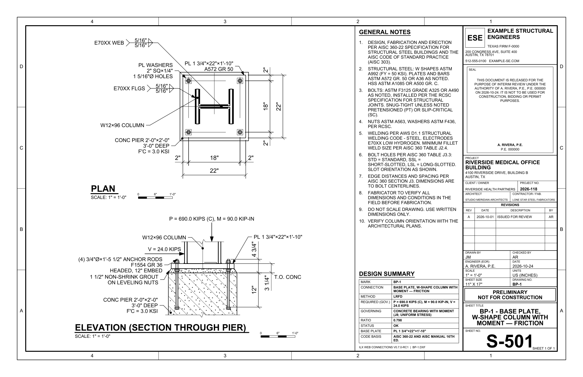
The drawing sheet places both views beside the general notes and the design summary: mark, connection, method, required strength (P, M, V of the governing combination), governing check, ratio, status and base plate. Drawing (DXF) gives the same sheet as a DXF file.
The calculation report is titled Column Base Plate. Its input summary covers the column, loads, plate, concrete support, bearing, grout, anchor rods, holes and washers, rod projection and length, shear transfer and welds, and the governing code for anchorage. See Reports.
Auto-design and batch for base plates #
Auto-design searches:
- Plate thickness from 1/2 in. to 4 in. (the thinnest plate that passes);
- Rod diameter, 3/4 in. and larger;
- Embedment hef: 9, 12, 18 or 24 in.
It keeps the column, plate size N × B, rod pattern, pier, materials and loads. Base-plate fields cannot be pinned. The objectives are those of the other types (see Auto-design, compare and batch):
- Lightest (steel weight): plate plus rods;
- Fewest bolts: the rod count is fixed, so this ranks like the weight;
- Lowest cost (fabrication estimate): steel plus a per-rod allowance.
If no candidate passes, enlarge the plate or the pier yourself, then run it again.
Compare works as for other types. Batch runs a schedule of BP marks. The default columns are mark, column, PD and PL; add any other input field name, such as N, B, MD or rod_d, with + Column. Auto-design each mark sizes the plate thickness, rod diameter and embedment of each row for its own loads.
Limitations and documented deviations #
- Biaxial bending follows DG1 3rd Ed. §4.3.11 (Eq. 4-69). DG1 states that interaction for axial compression with the shear on a lug or friction. Under uplift or with the rods in shear ILX still reports it, with a note, and checks every elastic rod force.
- Symmetric pattern. Two rod lines, symmetric about the column; moment and shear are designed by magnitude. Perimeter rod patterns and the rows along the web of DG1 Ex. 4.7-7 cannot be entered.
- Not covered: embedded column bases, stiffened base plates, shear by plate-edge bearing (DG1 Ex. 4.8).
- Seismic design covers uniaxial bending, as DG1 Chapter 6 does. The AISC 341-22 D2.6b shear is generated for the strong axis only when you give the story height; otherwise it is the shear you enter. Anchor chairs and rod sleeves for the stretch length are not modelled. The ASD weak base is an ILX conversion of the LRFD-only DG1 example (see above).
- Plate bending. DG1 3rd Ed. App. B.4 two-way bending is an option for the n strip at the bearing interface. The tension interface uses the full B; the 45° width is advisory only.
- Triangular method. It is the DG1 2nd Ed. App. B.5 method. Whether the 3rd Ed. keeps it is not confirmed.
- Shear lug bearing area. Aef,sl uses the full lug depth below the grout. Some programs limit it to 2 tsl.
- Anchor reinforcement. An entered As stays an advisory strength, φ As fy. Designed bars (or pier bars) are checked for placement and development; shear hairpins are not designed, and pier ties are taken as developed by their 135° hooks.
- App. C stiffness covers exposed bases only (no blockout or embedded bases). Double-nut joints: fatigue (App. A.1.2) and punching below the heads are not checked.
- Grout strength is not used in bearing; the concrete f′c governs.
- Pier and footing are calculated alike, with the support concentric with the plate.
- Rods not in Table 14-1. Table 14-1 lists 3/4 to 2-1/2 in. rods (no 1-1/8, 1-3/8 or 2-1/4 in.). For other rods the hole and washer are yours; the prefilled values (holes d + 1-1/4 in. above 2-1/2 in., following Commentary C-J9.1; washers extrapolated) are not Manual values and the report says so until you enter them.
- F844 washers are drawn round in the plan (outside diameter as entered); plate washers are drawn square. The callout names them.
- Not checked: rod bearing on the plate hole and the column end finish (M2.6).
- Verification. Against AISC Design Examples J.6 and K.9, Design Guide 1 2nd Ed. Examples 4.1 to 4.11 and B.5, the SteelTube Institute HSS examples and published ACI anchorage examples. Three documented differences:
- DG1 Ex. 4.7, ASD rod tension: DG1 rounds Y before computing T.
- DG1 Ex. 4.9, lug bearing: DG1 uses ACI 349; ILX uses ACI 318-19 17.11.
- DG1 Ex. B.5.2, rod tension: DG1 uses a bearing stress different from the one it computes.
See Verification.